
Home automation
Since about 2 years back we have had a Telldus home automation system installed. This uses radio frequency signals to control wall plugs and get information as humidity and temperature from sensors. There are a lot of products available that uses the 433 MHz standard and can be hooked up to the system. Yet after a while I got interested into building some devices on my own using the Arduino microcontroller. I will divide this post into a two part series, the first part will focus on the hardware and the signal/data acquisition and the second part will focus on the software in the Ardunio microcontroller.
The basic hardware components that I use for this type of projects are:
- 433 MHz receiver module
- Voltage regulator
- 9V Battery
- Arduino Uno
Lets start by breaking down the components and what their purpose is.
433 MHz receiver module
Since all communication is broadcasted using a 433 MHz transmitter from the Telldus system, we need to have a receiver that captures the signals. With the help of a small antenna the 433 MHz receiver listens and then uses ASK(Amplitude shift keying) modulation to process the signals. The inputs are sinusoidal signals that oscillates at 433 MHz and the unit takes these and converts them and outputs digital signals.
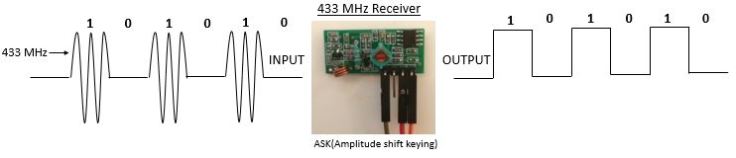
There are 3 connections that you need to have for the 433 MHz receiver. 5 VDC, Ground and Data.

Voltage regulator
When I first started to make trials with the Arduino and the 433 MHz receiver I was struggling with what I though was bad reception. Initially my hypothesis was that the antenna was not performing correctly or that the circuit board was damaged. Probably out of 20 sent data packets from the transmitter 1 got through and could be recognized by the Arduino. Once I hooked my oscilloscope on to the data pin I could see that there was a lot of noise coming from the receiver. During these trials I was powering my Arduino from the USB port of my computer and powering the 433 MHz receiver from the 5VDC on the Arduino. This was not a good idea.. Instead I made an alteration to the circuit and added an adjustable voltage regulator which was feed from an external 9VDC battery. I adjusted the regulator down to 5VDC, ensured that it was connected to common ground (Same as the Arduino),connected it to the 5VDC pin on the 433 MHz receiver and voila! The signal was clean. I have seen in many other tutorials that people directly connect the 433 MHz receiver to the Arduino, my system has been working a lot more reliable after getting a “clean” power supply.

In this specific project I am using an adjustable voltage regulator that has build in decoupling capacitors.
Arduino Uno
The receiver will output a number of digital pulse that is required to be interpreted, collected and formatted by the Arduino. The protocol that many of the 433 MHz receivers are using consists of wire messages that is encoded using Manchester code that in the end will build up a 32 bit packet. Before each data packet is sent out there is a latch signal sent out to “wake up” the devices. The latch signal consists of a 275 µs HIGH signal followed by a 2675 µs LOW signal.
After the latch signal the wire messages follow. A logical 1 is made up out of a HIGH signal for 275 µs and a LOW signal for 275 µs. A logical 0 is made up out of a HIGH signal for 275 µs and a LOW signal for 1225 µs.
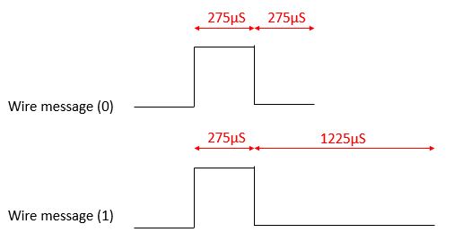
Since the messages are encoded using Manchester code two wires messages are required for each bit of the data packet. Wire message 01= 0 and wire message 10= 1.

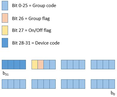
So in fact there will be 64 wire messages going into the Arduino that needs to be encoded to complete the 32 bit packet. Bits 0-25 of the data packet consists of a group code, bit 26 is a group flag, bit 27 is On/Off flag and bit 28-31 is a device code.
The complete circuit
After hooking everything up this is what it looks like:

It is worth mentioning the importance to keep all of the devices to the same ground. In the next part of this series I will be breaking down the software that is required in the Arduino microcontroller.
To be continued…

1 Pingback